
Casing pipe is used for lining the complete borehole which has been dug into the ground to procure oil. Similar to the drill pipe, the oil well casing pipe is also subjected to axial tension, therefore they are required to be made from high-quality strong steel material. OCTG casing is large diameter pipe which are held in place in the borehole using cement.
The diameters of OCTG casing pipe range from 4.5″ to 36″. The well-cemented pipe acts as the structural component of the well and offer hole integrity. They prevent the well from collapsing when the drilling process is on. Good quality, well cemented casing can stay in place for the whole life of the well.
Casing pipe installation
Installation of casing pipe involves assembling series of steel pipes comprising individual joints, with varying lengths depending on the type of casing string. These joints feature male threads on each end, connected together using short sections of double-female threaded pipe known as collars or couplings. Some manufacturers offer pipe joints with pre-attached female threads on one end. Each pipe string has a decreasing diameter compared to the previous one, tapering the strings down into the wellbore.
Casing strings and drill strings alternate within the wellbore. After completing a section of drilling, the drill string is removed from the hole, a new casing string is inserted and cemented, and then the drill string is re-inserted with a smaller bit to accommodate the narrower pipe.
Once inside the wellbore, steel pipe casing strings are cemented in place around the outside diameter of the pipe. This is achieved by pumping a mixture of cement slurry and drilling mud down the casing string with a bottom plug and a top plug. The mixture flows through the casing, filling the space between the outside of the pipe and the well wall (the annular space/annulus). Following cementing of the casing pipe, drilling operations can resume.
Tubing is inserted inside the wellbore through the oil well casing pipe, which helps the transportation of the hydrocarbons to the surface. It is pipe either used for transporting natural gas or crude oil to the facilities for further processing after the drilling is complete. Similar to the drill pipe and casing, tubing also is subjected to high pressure during the extraction process, and hence needs to be thick, strong and sturdy. Production tubing is available in various sizes ranging from ¾” to 4 ½”.
Casing sizes:
Sizes: 13-3/8” thru 4-1/2” Casing
Grades: J-55, L-80, N-80, And P-110
Range: Range 1 thru Range 3
Connections: BTC, STC, LTC, NUE, EUE
Bands: White, Yellow, Blue, and Green
Tubing sizes:
Sizes: 4-1/2” thru 2-1/16”
Grades: J-55, L-80, N-80, And P-110
Range: Range 2
Connections: BTC, STC, LTC, NUE, EUE
Bands: White, Yellow, Blue, and Green
Casing Pipe Application:
|
Road Bore Casing |
Water Well Casing |
|
Culverts Casing |
Open Cut Casing |
|
Oil and Gas Transmission Pipeline Casing |
Drilling Casing – Surface Casing – Rathole Casing |
|
Tunnel Casing |
|
Casing Manufacturing Process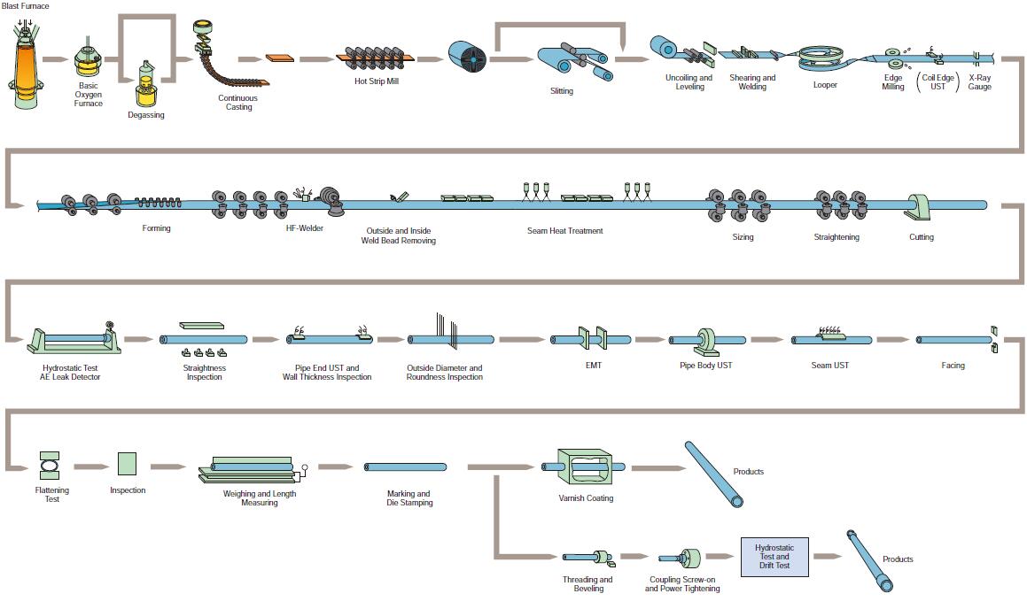
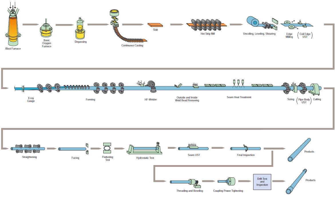
❶ Steelmaking
Degassing and desulfurizing of the metal during the steelmaking process produce clean steel with low non-metalic inclusions and better surface finish.
❷ Hot Rolling
Advanced hot rolling results in hot coil with a fine grain structure and high dimensional accuracy.
❸ Spiral Looper
The spiral looper supplies a steady feed of coil downstream to the continuous edge milling, pipe forming and welding stands.
❹ Forming Stands
Heavy duty stands accurately form the incoming coil into pipe having a wide range of wall thickness and outside diameter.
❺ HF-Welder
“Welding Condition Monitoring and Controling System”, developed by NSSMC, produces high quality welds. Seams are inspected by ultrasonic testing.
❻ Welded Seam Heat Treatment
Heat treatment in the welded zone stabilizes the microstructure and gives it the same physical properties as the base metal. The exact seam position is determined by optical sensors for seam heat treatment, and ultrasonic and hydrostatic testing.
❼ Non-destructive Testing
Every length and entire surface of each T.U.F.-Pipe is subjected to a full line-up of non-destructive tests.
❽ Automatic Inspection
Every pipe is given a comprehensive check using automatic inspection equipment.
❾ Monitoring and Tracking System
T.U.F.-Pipe is monitored and tracked at every stage of production by on-line computers. All manufacturing data is stored by computer and can be made available in any form required by the customer.
❿ Marking
Automatic stencilling and die-stamping machines identify and clearly mark every pipe.
⓫ Threading
Advanced NC lathes cut high precision threads to order. Connectors for large O.D. casings are also available. The use of thread protectors is recommended to prevent damage to the connectors during handling, loading and pipe rolling.
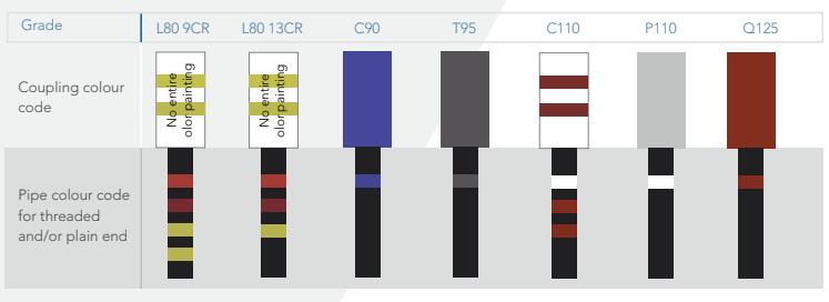
Casing Pipe Coupling colour code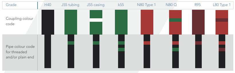
Casing Pipe Chemical Composition, Mass Fraction(%):
|
|
|
C |
Mn |
Mo |
Cr |
Ni Max |
Cu Max |
P Max |
S Max |
Si Max |
||||
|
Min |
Max |
Min |
Max |
Min |
Max |
|
Max |
|||||||
|
H40 |
- |
- |
- |
- |
- |
- |
- |
- |
- |
- |
- |
0.030 |
0.030 |
- |
|
J55 |
- |
- |
- |
- |
- |
- |
- |
- |
- |
- |
- |
0.030 |
0.030 |
- |
|
K55 |
- |
- |
- |
- |
- |
- |
- |
- |
- |
- |
- |
0.030 |
0.030 |
- |
|
N80 |
1 |
- |
- |
- |
- |
- |
- |
- |
- |
- |
- |
0.030 |
0.030 |
- |
|
N80 |
Q |
- |
- |
- |
- |
- |
- |
- |
- |
- |
- |
0.030 |
0.030 |
- |
|
M65 |
- |
- |
- |
- |
- |
- |
- |
- |
- |
- |
- |
0.030 |
0.030 |
- |
|
L80 |
1 |
- |
0.43 |
- |
1.90 |
- |
- |
- |
- |
0.25 |
0.35 |
0.030 |
0.030 |
0.45 |
|
L80 |
9 Cr |
- |
0.15 |
0.30 |
0.60 |
0.90 |
1.10 |
8.00 |
10.0 |
0.50 |
0.25 |
0.020 |
0.010 |
1.00 |
|
L80 |
13 Cr |
0.15 |
0.22 |
0.25 |
1.00 |
- |
- |
12.0 |
14.0 |
0.50 |
0.25 |
0.020 |
0.010 |
1.00 |
|
C90 |
1 |
- |
0.35 |
- |
1.20 |
0.25 |
0.85 |
- |
1.50 |
0.99 |
- |
0.020 |
0.010 |
- |
|
P110 |
- |
- |
- |
- |
- |
- |
- |
- |
- |
- |
- |
0.030 |
0.030 |
- |
|
Q125 |
1 |
- |
0.35 |
- |
1.35 |
- |
0.85 |
- |
1.50 |
0.99 |
- |
0.020 |
0.010 |
- |
Note:If the wall thickness is less than 17.78mm, the molybdenum content of the C90-1 steel grade has no lower limit.
Dimension Tolerances:
|
Casing Pipe |
Tolerance |
|
|
Outside Diameter |
Pipe Body |
D≤101.60mm,±0.79mm |
|
D≥114.30mm,+1.0%, -0.5%D |
||
|
Coupling |
±1%D |
|
|
Wall Thickness |
0, -12.5%t |
|
|
Weight |
Single Lengths |
+6.5%,-3.5% |
|
Carload Lots or Order Quantity |
≥18144 kg(40000ib),0,-1.75% |
|
|
<18144 kg(40000ib),0,-3.5% |
||
Tensile and Hardness Requirements:
|
Steel grade |
Type |
Total elongation under load (%) |
|
min |
Hardness max |
||
|
min |
max |
HRC |
HBW |
||||
|
H40 |
- |
0.5 |
276 |
552 |
414 |
- |
- |
|
J55 |
- |
0.5 |
379 |
552 |
517 |
- |
- |
|
K55 |
- |
0.5 |
379 |
552 |
655 |
- |
- |
|
N80 |
1 |
0.5 |
552 |
758 |
689 |
- |
- |
|
N80 |
Q |
0.5 |
552 |
758 |
689 |
- |
- |
|
M65 |
- |
0.5 |
448 |
586 |
586 |
22 |
235 |
|
L80 |
1 |
0.5 |
552 |
655 |
655 |
23 |
241 |
|
L80 |
9 Cr |
0.5 |
552 |
655 |
655 |
23 |
241 |
|
L80 |
13 Cr |
0.5 |
552 |
655 |
655 |
23 |
241 |
|
C90 |
1 |
0.5 |
621 |
724 |
689 |
25.4 |
255 |
|
P110 |
- |
0.6 |
758 |
965 |
862 |
- |
- |
